
Chapter 8
What is CAPACITANCE ?
Capacitance plays a very important role in electronics together with resistance and other circuit properties. I will try to explain to you some basics about it and show you how important it really is in electronics.
This is were electronics begins to get a little more complicated and to some people this tutorial might not sound very exciting, but if you truly want to understand everything and make ideas work from scratch, you will need to understand it all, even the boring sections.
It takes a lot of reading and studding before you can start to design useful circuits.
First of, CAPACITANCE is represented with the letter C in electronics, just so you know.
An electronic device/component that sooner or later you will or might have already seen and worked with is a device that stores energy in an ELECTROSTATIC field inside of it and accepts a charge of electricity or returns the charge back to the circuit, depending on if it is charging or returning the constant feeding voltage.
Basically it is like a mini battery, it stores energy over short periods of time, temporarily, and some for longer periods of time, some devices charge and release on a regular interval.
It all depends on what type of capacitor you are using as there is many of them out there, different ones made for different purposes. Capacitors behave similar to inductors, they oppose the change in voltage in the circuit or release it back to the circuit depending on the situation.
Most capacitors are solid state devices, this means they don't have any moving parts inside of them, but there are some that do have moving parts inside of them. To give you an example, one such device is called a turning capacitor. With this type of capacitor you use a knob to operate it. You probably have one of these types of capacitors in your radio, and they are used to select frequencies with. As you turn it, you can work with a different frequency at a time, but you can not hear others.
What is a CAPACITOR ?
In the old days the Capacitor was called a condenser, but we don't use that name anymore. So what is a capacitor ?
A capacitor is a special electrical component that you can use to charge it with electrons, or energy in the circuit. Once you charge the capacitor to it's maximum, it stays charged until you discharge it. It was called a capacitor, because this device possesses capacitance. Capacitance is the inherent property of electric circuit that opposes change in voltage. Property of circuit whereby energy may be stored in electrostatic fields and use to do something with later on or immediately.
The schematic symbol for a capacitor is:
The basic capacitor is constructed out of two metal plates separated by an insulator or air. insulator: substances containing very few free electrons and requiring large amounts of energy to break electrons loose from influences of nucleus.
This separator is called the DIELECTRIC. A potential voltage connected across these plates produces the following action.
I did this picture below to illustrate my example better in Photoshop.
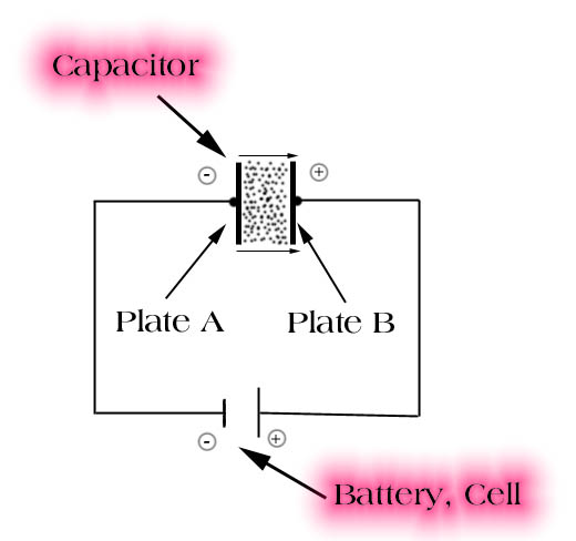
Ok, imagine that we took a small 9V cell, not a battery :- ), and connected two wires to it and those in turn are connected to our capacitor, what kind does not matter for now.
The electrons from the negative battery terminal or lower potential terminal flow through the wire instantaneously to the capacitor and hit plate A of the two plates, A and B or 1 and 2.
The plate on the other side of plate A, the one that is separated by the DIELECTRIC, actually both are, is very close, but not close enough to reach the plate A, so the current can't flow to the other side of the capacitor to plate B. However plate B is within the range of the established electrostatic field and that I will teach you about later.
The electrons on plate B are repelled by the electrons on plate A and are attracted to the positive terminal of the battery, the one with the higher terminal potential thus the reason why we have + and - on batteries.
The electrons are distorted toward the positive plate. This creates a potential difference between the two plates and the capacitor is said to be CHARGED. Please also note that the charge of the capacitor is opposite in polarity compared to the source voltage from the battery.
The AMPS or currents do flow or does flow in the circuit but only during the charging of the capacitor. Once the capacitor is charged, or fully charged, the current stops flowing and is at zero and we of course still have volts in the battery.
If you are confused about the above, maybe if I refresh your mind about what repelled means you will understand it faster. repelled: to drive back, turn away, reject, look it up in the dictionary.
If you removed the capacitor from our circuit, it would still remain charged and could be used as a source of voltage, not for very long, but could be used.
Word of caution; capacitors, especially the ones used in high powered circuits or voltage circuits can and most of the time do retain a great deal of energy when fully charged. They are very dangerous and it is best to always discharge them by the process of shortening before handling them with your bare hands.
Capacitors are also used to act as filters, and are used in high frequency applications like radios and radio transmitters. If you don't know what you are dealing with, don't touch it or it will be the last thing that you will ever touch.
All capacitors have a working voltage direct current or (WVDC) rating on them, which is the specified voltage the capacitor can handle or withstand without destructing it's self. There is also WVAC, for A/C circuits.
It is very important that the capacitors specification is obeyed and that the electrician replaces a bad capacitor with the right WVDC rating.
When a capacitor is discharged in the circuit, the energy stored within it is returned back to the circuit. You have to keep in mind that capacitor components are made differently for different uses. Some are rated to work within a certain Voltage ratings, if the applied voltage exceeds this rating, you will burn it up and damage the circuit.
If they fail to do so, sparks or arcing will result between the two plates and possibly start a fire, or explosion.
Some capacitors will and can remain charged very long after you turn off the circuit from the voltage source. Again discharge them before handling with your bare hands, sometimes more then once to be on the safe side. Use a insulated screwdriver and touch the LEAD of the capacitor, this will discharge it.
What is the FARAD ?
The unit of measure FARAD is used in capacitors to tell how much electrical energy that capacitor can store. It was named in honor of Michael Farad.
A value of 1 FARAD is a very large unit, and that is why most of the time you
will be working with much smaller units of measure.
1 FARAD (F) is 1
1 microfarad is 1/1,000,000 or basically 1 millionth of a farad
1 picofarad is (1/1,000,000 of 1/1,000,000 of a farad)
And a FARAD is ?
When one ampere of charging current flows and when the applied voltage is changing at a rate of one volt per one second we have 1 FARAD.
Looking at it from a mathematical angle, here is the equation to figure out Capacitance.
C = unit of measure in Farads
i = charging current in amps
v = the change in volts
t = the change in time in seconds
C =
i
----- divided by
v/t
or i divided by ( v divided by t )
Example:
Question: What is the capacitance of a capacitor when:
Charging current is 350 milliamperes <-- this is i
Voltage changes at a rate of 35 volts <-- this is v
Frequency is 185 hertz <-- this is t
The i and v SHOULD BE OBVIOUS, the little twist that you might be confused is the 185 hertz as that doesn't sound like a unit of seconds that you probably would expect, but hertz are cycles of frequency and you will many time see this in examples instead of a time values like 5 seconds or 60 seconds.
The first thing you need to do is change all given values to the basic number.
350 milliamperes is 0.35 amps, remember there is 1000 milliamperes to 1 amp.
35 volts is already in a basic number.
and 185 hertz is 0.0185 seconds.
10,000 hertz or 10 Kilohertz is 1 second, not really sure why, but this is how I learned it and it is correct as far as I know.
C =
.35
-------- divided by
35 / 0.0185
= 0.000185 farads or 185 microfarads
Another way to find out Capacitance is with a method of finding out the charge or quantity of electrons that the capacitor can accept per volt of potential applied to it in a circuit.
in this example:
C = capacitance in farads
Q = coulombs ( you should know what that is by now, if you don't remember,
please look it up in my previous chapters or the local library, also physics
books and chemistry books should have this )
V = volts
Working example:
You know that a capacitor that you hooked up to a circuit will accept a charge of .35 coulombs with an applied voltage of 350 volts, to find out the capacitance, you do this:
C =
.35 coulombs
------- divided by
350 volts
= 0.001 farads or 1000 microfarads ( Remember that it takes 1,000,000 microfarad units to make 1 FARAD ) 1 FARAD can kill you.
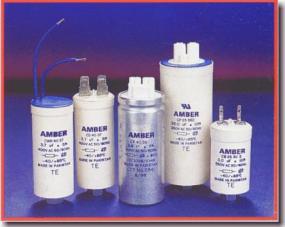
TYPES of Capacitors ?
There are many different types of capacitors made for different applications in the electronics fields, and to be honest with you I don't know them all. Some of the most common types are:
VARIABLE CAPACITORS
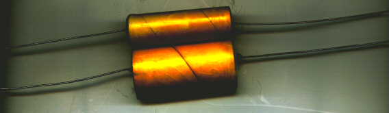
FILM CAPACITORS
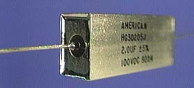
HERMETIC SEAL
PAPER CAPACITORS
CERAMIC CAPACITORS
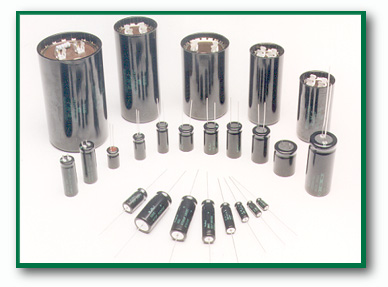
ELECTROLYTIC CAPACITORS
MICA CAPACITORS
Large industrial type CAN CAPACITORS
MINIATURE CAPACITORS, used in computer manufacturing of all kinds of circuit
boards, like motherboards.
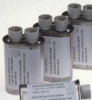
MICROWAVE OVEN CAPACITORS
As you start to make projects you will get familiar with many different ones
over time, don't try to learn them all now, real life experience will teach you
a lot in addition to reading books.
What are the "CHARACTERISTICS" that make up a Capacitor ?
You can make your own capacitor if you want, as a matter of fact that is how they were invented by scientists making them in the lab first before they go to any sort of production.
The 3 major characteristics are:
PLATE AREA
SPACING BETWEEN THE PLATES
and KIND OF Dielectric used to separate the plates
Plate Area: The capacitance of a capacitor will be increased as
you increase the plate area, simply because you can store more energy into
them. One good example that will show you this in real time without
making any type of capacitor and comparing it with a smaller one is to use a
variable capacitor.
This is the one that has rotating plates, as you turn the knob the plates move against the other stator plates and a larger area is being covered or used. Turn it the other way and a smaller area is used, cool isn't it ?
These types of capacitors almost give you many different ones all in one, by turning the knob it's like changing a capacitor without doing so, you should use this type of capacitor whenever this circuit effect is needed.
Spacing between the plates: Spacing is not the dielectric, it is simply the distance used to separate the two plates from each other, in addition to spacing there is also dielectric material used, that's next.
To put it into simple words, as the plates are closer together, capacitance is increased, as they are moved apart more, capacitance is decreased. Molecular distortion and the ability for the plates to store more energy will be less as the plates are separated more, more if separated less.
And now the DIELECTRIC: The dielectric values of different materials are all compared back to AIR or Vacuum. In the beginning simple air capacitors were used. Later it was found that other materials worked better then AIR and they could increase the capacitance of the capacitor.
Because of how different materials are made and of their molecular formation, they work better storage abilities when used as a dielectric.
Because AIR or Vacuum was used first, the below chart show these two basic values comparing the other materials all back in respect to Air or Vacuum.
So Air/Vacuum is our basic Value of 1, just like FARAD is our basic value of 1 in capacitance.
Material |
Dielectric Constant (k)
--------------------------------------------------
Vacuum
1.0000
Air
1.0006
Waxed Paper
3 to 5
Glass
5 to 10
Mica
3 to 6
( note that some capacitors are named Mica because of the material used in
dielectric )
Rubber
2.5 to 30
Wood
3 to 8
Pure Water
81
FIXED FILM CAPACITOR DIELECTRICS examples:
Polyester (Mylar) Film:
A good general purpose plastic dielectric with relativity low cost and
high volumetric efficiency.
Still the most popular of the capacitor dielectrics. Available in both
Metallized Polyester Film and
Polyester Film & Foil designs.
Combination Film:
Combination Polyester (Mylar) and Polypropylene. Extremely low
temperature coefficient in the
0° C to 85° C temperature range. Volumetric efficiency similar to
Polycarbonate. Available in
both Metallized and Foil designs.
KF (Polymer) Film:
Extremely high volumetric efficiency with about 4 times the "K
Factor" of mylar, making it about
1/4 the size. Higher DF and lower IR are its disadvantages along with cost.
Polycarbonate Film:
Lower DF, higher IR, better temperature coefficient and better stability
than mylar with a slightly
lower volumetric efficiency. Second most popular Dielectric. Available in
both Metallized
Polycarbonate Film and Polycarbonate Film & Foil designs. Polycarbonate
capacitors have a
100% voltage rating from -55° C to +125° C.
Kapton Film:
Electrical properties similar to Mylar with a much higher operating
temperature going up to 250°
C. A higher cost than mylar limits its use.
Polypropylene Film:
Very good temperature coefficient high IR, and low DF make it good for AC
operation. Usable to
105° C without derating. Has become increasingly popular for AC
applications. Available in both
Metallized Polypropylene Film and Polypropylene film & Foil
constructions.
Polysulfone Film:
Electrical properties similar to polycarbonate with a very good
temperature coefficient and
higher operating temperature. Very limited availability in the last few
years has limited its use.
Available in both Metallized Polysulfone Film and Polysulfone Film &
Foil designs.
Polystyrene Film:
Very good electrical properties and excellent stability are its
advantages. Its big disadvantage is
its operation is limited to below 85° C and it is available in Polystyrene
Film & Foil construction
only.
SuperMetallized Polypropylene Film:
A very high current design for very high frequencies up to 1 Megahertz.
The ultimate in high
current capacitors. They are used for input filtering, high frequency
transformer DC blocking and
output filtering. They are dry-section non-polar metallized film dielectric
with special high current
end terminations resulting in very low ESR values and very high DV/DT
ratings. Larger than
SuperMetallized Polypulse. Also popular in snubber applications.
SuperMetallized Polypulse Film:
Developed by American Capacitor specifically for switching power supply
type applications.
They are used for input filtering, high frequency transformer DC blocking
and output filtering.
They are dry-section non-polar metallized film dielectric with special high
current end
terminations resulting in very low ESR values and very high DV/DT ratings.
They are
significantly smaller than metallized polypropylene capacitors and have a
100% voltage rating
from -55° C to +125° C. Capacitance change over temperature is 4 times
better than with
polypropylene.
Teflon Film:
The best electrical properties of all the Dielectrics. Extremely high IR,
low DF and operation to
250° C. Available in both Metallized Teflon Film and Teflon Film & Foil
constructions.
Paper Film:
Paper or Kraft Paper is the oldest of the film capacitor dielectrics. It
is available in both
Metallized Paper and Paper & Foil constructions. The paper must be
impregnated with Epoxy,
Wax, Oil, or other suitable impregnate. It is still popular for high voltage
and AC rated capacitors
operating at lower frequencies. Paper is also wound with plastic dielectrics
in combination
dielectric capacitors.
There are many different materials that can be used for the dielectric, I can't remember them all.
If you know of any others that I missed, please let me know, I am not sure if silicone is used and what it's value is, if you know, contact me so that I can put this into this Table. The materials used in dielectric are called dielectric constants. Some capacitors have several different constants mixed and used as the dielectric.
If you make a home made capacitor and want to know what it's capacitance is, here is the equation to find that out with:
k = dielectric constant
A = area of one plate in square inches
n = number of plates
d = distance between the plates in inches
.2249 = a factor used to convert from metric to British units of
measurement.
C =
k * A (n-1)
-------------- divided by
d
TECHNICAL TERMS
These technical terms were taken off of the http://www.AmericanCapacitor.Com web site for reference only, I thought it was very usefull information, so it's here also, but not as easy to understand as my examples :- )
Capacitance:
A measure of the energy storage ability of a capacitor, given as C = K A/D, where A is the area of the electrodes, D is their separation, and K is a function of the dielectric between the electrodes. The formula yields a result in farads (F ), but a farad is so large that the most commonly used values are expressed in microfarads ( µf = 10-6F ) or picofarads ( pf = 10-12F ).
Working voltage (Wvdc, Wvac):
The maximum continuous voltage that should be applied to a capacitor. Rated voltages for DC and AC operation are usually not the same.
Temperature Coefficient (TC):
The change in capacitance with temperature expressed linearly as parts per million per degree centigrade (PPM/°C), or as a percent change over a specified temperature range. Most film capacitors are not linear and TC is expressed in percent.
Dissipation Factor (DF):
A measure of the power factor (or losses) of a capacitor, given as DF = 2 P fRC X 100%, where R is the equivalent series resistance of the capacitor, f is the frequency, and C is capacitance. Dissipation factor varies with frequency and temperature.
Equivalent Series Resistance (ESR):
A measure of the total lossiness of a capacitor which includes the leads, electrodes, dielectric losses, leakage (IR) and most important, the end spray connecting the leads to the metallized film. The lower the ESR the higher the current carrying ability the capacitor will have.
Insulation Resistance (IR):
A measure of the resistance to a DC current flow through the capacitor under steady state conditions. Values for film and ceramic capacitors are usually expressed in megohm-microfarads for a given design and dielectric. The actual resistance of the capacitor is obtained by dividing the megohm-microfarads by the capacitance.
Dielectric Absorption (DA):
An apparent "recovery voltage" measured after the capacitor is discharged and expressed as apercent of the initial charge voltage. DA is due largely to the dipole moment of the dielectric and to lesser degree the migration of free electrons to the surface of the dielectric.
Volumetric efficiency:
Energy density in µf-volts per cubic inch, from: (capacitance) X (working voltage) ÷ (volume).
Longer capacitors are more efficient than shorter units, because of volume used by encapsulation and unused dielectric at the capacitor ends (The margins). Cylindrical units have a smaller volume than rectangular units, although rectangular units can be stacked more compactly.
Corona:
Any electrically detectable, field intensified ionization that does not result immediately in complete breakdown of the insulation and electrode system in which it occurs. Its incidence can be reduced or avoided through special designs.
Pulse Operation:
Capacitors subjected to DC pulses or non-sinusoidal voltages with fast rise
or drop
times (High DV/DT) will be exposed to high current. This current must be limited
to within the maximum peak current allowed.
These peak currents refer to an unlimited number of pulses charging or
discharging the capacitors.
AC VOLTAGE:
The sum of the DC and Peak AC voltage applied to the capacitor should not exceed the rated DC voltage, nor should the RMS voltage exceed the Corona Start Voltage.
I RMS:
The maximum RMS ripple current in amps at a given frequency.
I PEAK:
The maximum peak current in amps @ +25° C for non-repetitive pulses or where the pulse time off is sufficient to allow cooling so overheating will not result.
DV/DT:
Is the maximum allowed change in volts per microsecond at the rated voltage.